INRAT · Transport Canada · CARS Reference

Canadian IFR Cheat Sheet

Key numbers, rules, and procedures for the INRAT written exam — based on CARS, TC AIM, and Nav Canada. All values are Canadian-specific.

This INRAT cheat sheet covers the 15 topic areas tested on the Transport Canada instrument rating written exam: airspace classes A–G, IFR equipment requirements, VOR/NDB/ILS/RNAV nav aids, weather minimums, fuel requirements, alternate aerodrome minima, approaches, flight plans, communication failure procedures, IFR currency, and cruising altitudes. Every figure includes its CARS or AIM reference.

Airspace
Low-Level Controlled Airspace
Base of controlled airspace2 200 ft AGL
Upper limit (low-level)Below 18 000 ft ASL
VHF/UHF airway width (each side)4 NM
VHF/UHF splay angle (each side)4.5°
LF/MF airway width (each side)4.34 NM
LF/MF splay angle (each side)
T-Routes (primary each side)4 NM
T-Routes (secondary each side)2 NM
MEA / MOCA protection (each side)5 NM
L-Routes (uncontrolled RNAV, GNSS req'd)Green dashed
High-Level Controlled Airspace
Southern Control Area (SCA)≥ 18 000 ft ASL
Northern Control Area (NCA)≥ FL 230
Arctic Control Area (ACA)≥ FL 270
Control Zones
Civil CTZ with TCA (radius)7 NM
Civil CTZ without TCA (radius)5 NM (some 3 NM)
CTZ ceiling (unless specified)3 000 ft AAE
Military CTZ radius10 NM
Military CTZ ceiling6 000 ft AAE
Control area extensions (base)2 200 ft AGL
MOCA Obstacle Clearance
Outside designated mountainous areas1 000 ft
Mountainous areas 2, 3, and 41 500 ft
Mountainous areas 1 and 52 000 ft
MOCA for T-Routes / L-Routes protects only 6 NM either side — does NOT splay.
Airway Dimension Diagrams
VHF/UHF Airway VOR to VOR

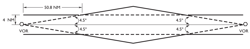
VHF/UHF Airway — VOR to VOR (4 NM each side, 4.5° splay)

LF/MF Airway VOR to NDB

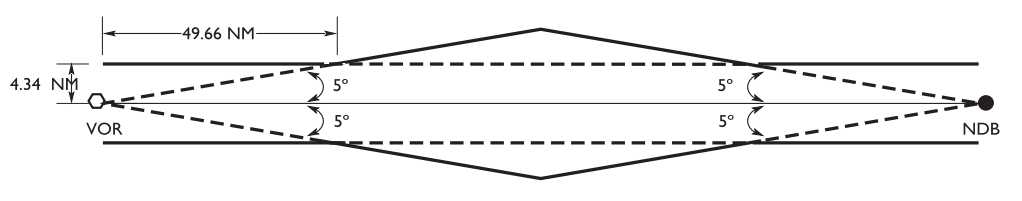
LF/MF Airway — VOR to NDB (4.34 NM each side, 5° splay)

LF/MF Airway NDB to NDB

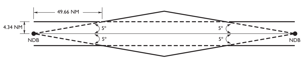
LF/MF Airway — NDB to NDB (4.34 NM each side, 5° splay)

T-Route Fixed RNAV

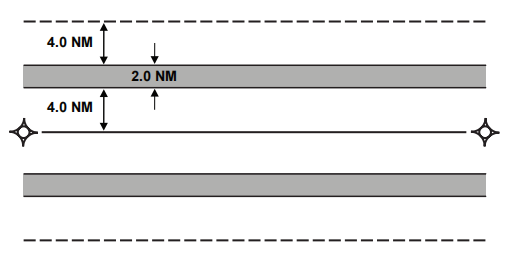
T-Route (Fixed RNAV) — 4 NM primary + 2 NM secondary each side

Airspace Class Summary
ClassTypeIFR
AHigh-level (≥18 000 ft ASL)ATC clearance req'd
BTCA (Terminal Control Area)ATC clearance req'd
CControlled with ATC serviceATC clearance req'd
DControl zoneATC clearance req'd
EControlled, no ATC svcATC clearance req'd
FSpecial use (advisory/restricted)Check NOTAM/AIP
GUncontrolledNo clearance (file itinerary)
IFR Equipment Requirements CAR 605.18
Required for IFR Flight (Day)
  • Attitude indicator
  • Vertical speed indicator (VSI)
  • Outside air temperature (OAT) gauge
  • Pitot heat (anti-ice for each ASI)
  • Vacuum / power failure warning device
  • Alternate static source (for altimeter, ASI, VSI)
  • Two-way radio (appropriate frequency)
  • Radio nav — enough redundancy to complete approach in IMC
  • Day VFR instruments: altimeter, ASI, compass, clock, VSI, turn coordinator
CAR 605.18 — IFR adds (c) through (j) to day VFR requirements
Night IFR — Additional Equipment
  • All day IFR equipment above
  • All night VFR equipment (CAR 605.16(1)(i) to (k))
  • Position lights, anti-collision lights
  • Landing light (for hire)
Class G Uncontrolled — Extra Required
  • ADF (functioning)
  • OAT gauge
Special requirement: CAR 605.18 — operating IFR in Class G
Inspection / Calibration Intervals
Altimeter (within tolerance)± 50 ft
Pitot-static system24 months
Magnetic compass12 months
Transponder24 months
GNSS database cycle28 or 56 days
Transponder Requirements
  • Required in Class A, B, and C airspace
  • Required within 12 NM of Class B aerodrome boundary
  • Mode C (altitude encoding) required in Class A, B, C
  • Emergency: squawk 7700
  • Communication failure: squawk 7600
  • Unlawful interference: squawk 7500
CAR 605.35
IFR Currency CAR 401.05
Instrument Recency Requirements

Within the preceding 6 months, the pilot must have completed all of:

Instrument approaches6 approaches
Holding proceduresRequired
Tracking using electronic nav aidsRequired
If recency has lapsed → must complete an Instrument Proficiency Check (IPC) with an authorized examiner.
IFR Flight Plan vs. Itinerary
Controlled airspaceFile IFR Flight Plan
Partly/wholly uncontrolled airspaceMay file itinerary
Inadequate comm facilitiesMay file itinerary
Canada ↔ Foreign stateFlight Plan required
An IFR flight plan is always required when operating in controlled airspace. An itinerary is only permitted when no ATC unit, FSS, or CARS is available.
VOR — VHF Omnidirectional Range
General
Frequency band112.0 – 117.95 MHz
Published airway accuracy± 3°
Underlined nav aidNo voice
Basis of Victor airwaysYes
1.23 × √AGL = Reception range (NM)e.g. at 3 600 ft AGL → 1.23 × 60 = 73.8 NM
VOR Check Tolerances
VOT check (180° TO / 360° FROM)± 4°
Ground check (published point)± 4°
Airborne check (published radial)± 6°
Visual airway check± 6°
Dual VOR check (Nav 1 vs Nav 2)Within 4°
If dual receivers differ by more than , one receiver may be out of tolerance.
Nav Aid Chart Symbols
Nav aid symbols

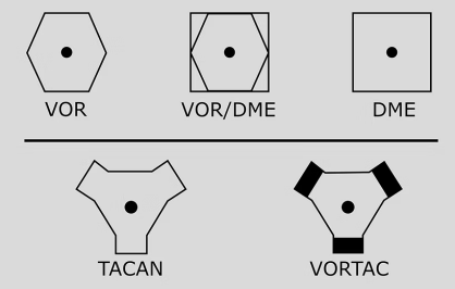
VOR, VOR/DME, DME, TACAN, VORTAC symbols

VOR chart symbology

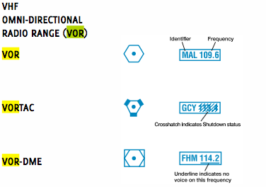
VOR chart symbology — underline = no voice

Time / Distance Calculations
Time to VOR (min) = seconds ÷ radials crossedCount radials crossed in a timed period
Dist to VOR (NM) = GS (kt) × Time (min) ÷ 60
Time to NDB (min) = seconds ÷ degrees RB changeRB = Relative Bearing change in that period
Dist to NDB (NM) = GS (kt) × Time (min) ÷ 60
NDB / ADF
NDB / ADF Basics
Frequency range190 – 515 kHz
Line of sight?No — ground & sky waves
Flight check — Approach± 5°
Flight check — En route± 10°
Fixed card ADF needleAlways points to station
RMI displayMag bearing TO/FROM station
Coastal refraction (pronounced when)< 30° to shoreline
ADF Errors
  • Mountain Effect — signal diffraction over terrain
  • Twilight / Night Effect — sky wave interference at sunrise/sunset
  • Shoreline Effect — refraction crossing coast at <30°
  • Bank Error — dip in needle when turning (fixed card only)
  • Thunderstorm Effect — needle attracted to storm; use higher frequency to reduce
Intercepting an NDB
Intercept relative bearing =Intercept angle
Example: On a 090° heading, station bears 060° RB, intercept angle = 30°. Set intercept heading so RB = 30°.
ILS / Localizer
ILS Localizer Coverage
Within ± 10° of centreline18 NM
Within ± 35° of centreline10 NM
LOC is full-scale deflection at ~2.5° from centreline. Fly the needles, not the heading.
ILS Categories
CategoryDHRVR / Visibility
CAT I200 ftRVR 2 600 ft (½ SM)
CAT II100 ftRVR 1 200 ft
CAT III< 100 ft / 0RVR < 1 200 ft / 0
Aircraft and airport must both be certified for CAT II / III
DME — Distance Measuring Equipment
DME Tolerances & Use
Accuracy tolerance± 0.5 NM or 3%
1 NM equals6 076 ft
Max slant range errorDirectly overhead
Least slant error (where)Far away, low altitude
DME from TACANPair frequency on chart
GPS may be used as a substitute for DME, VOR, VOR/DME and ADF — provided RAIM is available and fixes are from a current database.
DME Arc Technique
Lead radial turn = (GS ÷ 200) × turn radius correctionFor a standard 30° bank, lead ≈ 0.5% of GS in NM
  • Track a constant DME distance from a VOR/TACAN
  • Turn 10° toward station when DME increases; away when decreases
  • Use CDI for final course intercept from the arc
MSA — Minimum Sector Altitude
Calculated fromCentre of aerodrome
Radius25 NM
Obstacle clearance provided1 000 ft
MSA is for emergency use only — does not guarantee nav signal reception or ATC coverage.
GPS / GNSS
Satellite Requirements
3D position fix4 satellites
RAIM integrity monitoring5 satellites
FDE (Fault Detection & Exclusion)6 satellites
Handheld GPS units do not have RAIM — restricted to VFR only.
CDI Sensitivity (Full-Scale Deflection)
En Route± 5.0 NM
Terminal (within 30 NM dest)± 1.0 NM
Approach (final segment)± 0.3 NM
RAIM Alert Limits
En route2.0 NM
Terminal1.0 NM
Non-precision approach0.3 NM
RAIM Availability
Acceptable if unavailable ≤15 min in ETA ± 60 min
Approach RAIM check windowETA ± 15 min
Mid-flight RAIM checkRequired
Database update cycle28 or 56 days
If RAIM warning occurs while using GPS as primary nav, continue on traditional nav aids and inform ATC.
GPS CDI Scale Transition
GPS RAIM sensitivity table

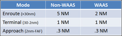
CDI sensitivity — Non-WAAS vs WAAS

CDI Scale Transition diagram

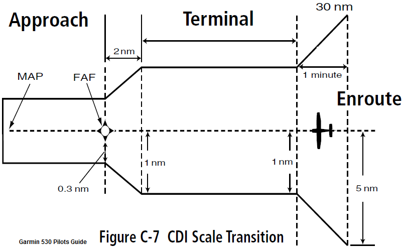
CDI scale transitions: En route (±5 NM) → Terminal (±1 NM) → Approach (±0.3 NM)

GPS RAIM check zones

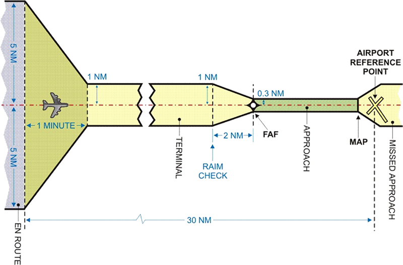
GPS RAIM check zones — terminal starts 30 NM from dest, RAIM check at 2 NM before FAF

GPS Approaches
  • Standalone RNAV (GNSS) — charted as "RNAV (GNSS) RWY XX"; T/Y-bar eliminates procedure turn
  • Overlay approaches — traditional VOR/NDB approved for GPS; charted as "NDB RWY 29 (GNSS)*"
  • Overlay: underlying nav aid need NOT be monitored
  • Overlay: can fly even if underlying nav aid is NOTAMd out of service
  • LNAV/VNAV and LPV = approaches with vertical guidance (APV)
Approach RAIM must be available within ± 15 min of ETA
GPS at Alternate Aerodrome
  • IFR-certified GPS unit required
  • RAIM must be predicted available at alternate ETA
  • One traditional nav aid approach must be available at alternate
  • Destination must have a traditional nav aid approach for flight planning
  • Check RAIM prediction at least once before mid-point of flight
GPS in Class G / Airways
  • IFR GPS can track airways & air routes as primary nav
  • Must still carry traditional nav aids to meet CARS
  • In uncontrolled (Class G): must have ≥ 1 functioning ADF
  • GPS may substitute for DME, VOR, VOR/DME, ADF — fixes must be in current database, no RAIM warning
  • 2 GPS approaches (dest + alternate) must be ≥ 100 NM apart
Weather — GFA & TAF
GFA — Graphic Area Forecast
Issued4× daily
Issued before validity period≈ 30 min prior
Valid altitude ceilingAt or below 24 000 ft
Heights reported inASL
Exception (ceiling, height, ground)CIG / HND / ABV GND / AGL
Winds included whenAbove 20 kt
Gusts included whenAbove 30 kt
Pressure unitsMillibars (e.g. 1013)
QS (quasi-stationary front)< 5 kt movement
LAYERS = cloud gaps< 1 000 ft thick
GFA alternate: no cloud <1 000 ft above lowest HAT/HAA, no CB, visibility ≥ 3 SM.
TAF — Aerodrome Forecast
Coverage radius5 NM of runway complex
RMKS section extends to10 NM
Validity period (civil)12 hours
International / Military TAF24 hours
Issued before validity period30 min prior
VRB wind (variable)< 3 kt, no direction
Permanent change indicatorsFM & BECMG
VV (Vertical Visibility)Constitutes a ceiling
TAF Terms for Alternate Planning
TermUse for alternateApplicable from/to
BECMG improvingMust meet alternate minimaEnd of BECMG period
BECMG deterioratingMust meet alternate minimaStart of BECMG period
TEMPOMust meet alternate minimaAny time during TEMPO
PROBMust meet landing minima onlyAny time during PROB
Weather Charts & Tables
IFR Outlook Criteria

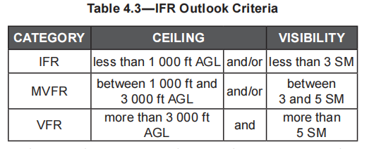
Table 4.3 — IFR Outlook Criteria (ceiling & visibility categories)

Sky Conditions for METARs

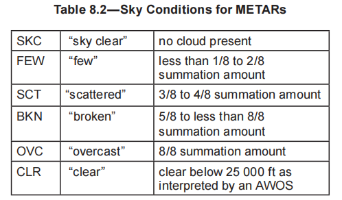
Table 8.2 — METAR sky condition codes

Non-convective Clouds

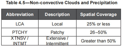
Table 4.5 — Non-convective cloud & precipitation coverage

GFA Weather Obstructions

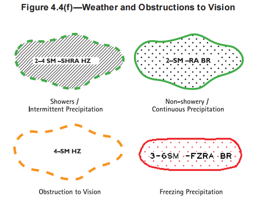
Figure 4.4(f) — GFA weather & obstruction symbols

Surface Winds

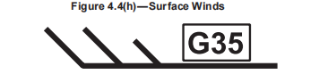
Figure 4.4(h) — Surface wind with gust (G35)

Surface Weather Map Legend

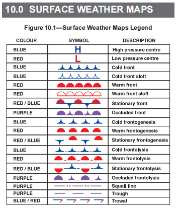
Figure 10.1 — Surface weather map symbols & fronts

Alternate Aerodrome Weather — Source Rules
  • TAF available — ceiling 500 ft above lowest HAT/HAA, vis ≥ 3 SM
  • Aerodrome Advisory forecast — ceiling 500 ft above lowest HAT/HAA, vis ≥ 3 SM
  • GFA only — no cloud <1 000 ft above lowest HAT/HAA, no CB, vis ≥ 3 SM
Ceiling minima are calculated using the procedure HAT or HAA. Round UP to next 100 ft.
Example: AAE 620 ft → ceiling value = 600 ft; HAA 621 ft → ceiling value = 700 ft.
Icing
Rime Ice
Temperature range0 to −15 °C
Associated cloud typeLayer cloud (stratus)
ExtentHorizontal (extensive)
Drop sizeSmall
Catch rateLow
AppearanceOpaque, rough, white
Clear Ice (Glaze Ice)
Temperature range0 to −25 °C
Associated cloud typeConvective (Cu, Cb)
ExtentVertical (extensive)
Drop sizeLarge
Catch rateHigh
AppearanceClear, smooth, heavy
Freezing rain from warm fronts = severe clear ice. Most hazardous icing condition.
Icing Reference Tables
Icing Types

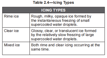
Table 2.4 — Icing types (Rime, Clear, Mixed)

Icing Intensity

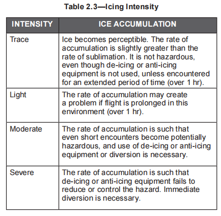
Table 2.3 — Icing intensity & required action

Catch Rate by Aircraft Surface
Thin wings / antennaHigh catch rate
Thick wings / windscreenLow catch rate
Known Icing Certification
Certified for known icing =Moderate icing capable
Hoar Frost
  • Forms in clear air when parked overnight below 0°C
  • Forms descending/climbing through temperature inversion (cold-soaked fuel in wings)
  • Can form on wing surfaces even when ambient temp is above freezing
VFR Over-The-Top (OTT) CAR 602.116
VFR OTT Requirements
Time of dayDay only
Phase of flightCruise only
Vertical distance from cloud≥ 1 000 ft
If between two cloud layers, gap must be≥ 5 000 ft
Flight visibility at cruising altitude≥ 5 SM
Destination Weather for VFR OTT

Destination must have sky condition SCT or CLR and visibility ≥ 5 SM with no forecast of precipitation, fog, thunderstorms, or blowing snow:

If TAF available — forecast period1 hr before to 2 hr after ETA
If GFA only — forecast period1 hr before to 3 hr after ETA
IFR Fuel Requirements CAR 602.88
Propeller-Driven Aircraft
With alternate: dest + missed approach + alternate +45 min reserve
No alternate filed: dest + missed approach +45 min reserve
Turbojet / Helicopter
With alternate: dest + missed approach + alternate +30 min reserve
No alternate filed: dest + missed approach +30 min reserve
MINIMUM FUEL

Aircraft fuel supply has reached a state where the flight is committed to land at a specific aerodrome and no additional delay can be accepted. Declare MINIMUM FUEL — not an emergency, but ATC must be informed.

MAYDAY FUEL (Emergency)

Declare MAYDAY when fuel remaining is less than required to safely complete the flight. This is an emergency — ATC provides priority handling.

Alternates & Approach Minima
Calculating Alternate Minima
Precision approach (base: 600-2)HAT + 300 ft / + 1 SM
If result < 600-2Use 600 ft / 2 SM
Non-precision (base: 800-2)HAT or HAA + 300 ft / + 1 SM
If result lower or higher than 800-2Always use the HIGHER value
For circling approaches, use HAA. For straight-in, use HAT.
Alternate Minima Tables
Alternate Aerodrome Weather Minima

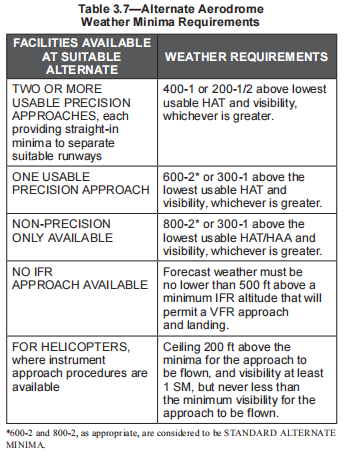
Table 3.7 — Alternate aerodrome weather minima requirements by facility type

Standard Alternate Minima

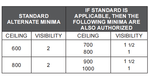
Standard alternate minima and authorized reduced minima

When an Alternate is Required
  • When the destination does not have a suitable forecast for the approach
  • When the TAF or GFA forecast shows conditions at or below alternate minima
  • When no instrument approach procedure exists at destination
Ceiling Value Rounding
HAA/HAT ending in 01–99 ft →Round up to next 100 ft
e.g. HAA 621 ft → ceiling = 700 ft; AAE 620 ft → ceiling = 600 ft
Decision Altitude vs. MDA
DA / DH — used forPrecision approaches (ILS, LPV)
MDA — used forNon-precision approaches
Missed approach — when to climbNot until MAWP
Missed approach — descent belowNever below DA or MDA
Contact Approach
Who initiatesPilot must request from ATC
Cloud clearanceClear of clouds
Flight visibility≥ 1 SM
Reasonable expectationContinue VMC to destination
Visual Approach
ConditionsVMC, ATC authorization
IFR flight planStill in effect
IFR Departures
Standard IFR Departure
Cross departure end of runway≥ 35 ft
Climb straight ahead before turningTo 400 ft AAE
Climb gradient required≥ 200 ft/NM
These are minima only — a published SID or obstacle departure procedure takes precedence.
Takeoff Minima
Governing factor for takeoffVisibility
Not assessed — default minimaRVR 2 600 ft or ½ SM
Asterisk (*) on plate (obstacles)Use climb gradient chart
Visibility Hierarchy (Takeoff)
1st priorityRVR value
2nd priorityAccredited observer (Tower / FSS / CARS)
3rd priorityPIC (200 ft between lights)
Can depart if RVR or accredited observer meets required minima.
Not Assessed Departures
  • "NOT ASSESSED" means departure has not been evaluated for obstacle clearance
  • PIC is responsible for determining minimum climb gradients
  • If "NOT ASSESSED" on plate → use ½ SM or RVR 2 600 ft
  • "*" on plate = obstacles in takeoff path → use climb gradient chart
Approaches are governed by RVR value. Takeoffs are governed by visibility.
Approaches
Approach Governing Factor
Approaches governed byRVR value
Landing — useDA (precision) or MDA (non-precision)
Missed approach — do NOT climb untilMAWP reached
SID amendmentSID NOT cancelled
NOTAM replacing/cancellingNOTAMR / NOTAMC
Visual Illusions on Approach
  • Upslope runway → illusion you are high → approach too low
  • Downslope runway → illusion you are low → approach too high
  • Narrow runway → feels farther away → approach too low
  • Wide runway → feels closer → approach too high
  • Rain on windshield → runway appears closer → approach too low
  • Featureless terrain (water, snow at night) → approaches too low
Visual Approach Slope Indicators
VASI Categories

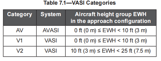
Table 7.1 — VASI categories by aircraft eye-wheel height (EWH)

PAPI Categories

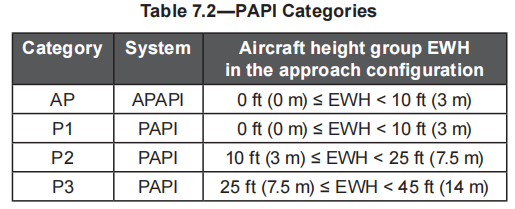
Table 7.2 — PAPI categories by aircraft eye-wheel height (EWH)

Holding Patterns
Standard directionRight turns
Standard leg time (below 14 000 ft)1 min
Standard leg time (at/above 14 000 ft)1.5 min
Bank angle (standard rate)3° per second
Missed approach: hold at MAWP or published holding fix. Do not start descent until EFC unless cleared for approach.
Procedure Turn
  • Not required if: "NoPT" on chart, radar vectors, timed approach, or holding in lieu
  • Must be completed on published side of course
  • Maximum distance from fix: as published (typically 10 NM)
  • T/Y-bar (GNSS approaches) eliminates procedure turn
Flight Plan & Clearances CAR 602.76 / 602.77
Closing a Flight Plan
Flight plan — arrival report not later thanSAR time or 1 hr after ETA
Flight itinerary — arrival report not later thanSAR time or 24 hrs after ETA
Not required when (flight plan)ATC unit / FSS / RAAS operating at aerodrome
Failure to close itinerary within 24 hrs of ETA will activate SAR.
Amending an IFR Flight Plan

Notify ATC as soon as practicable of changes to:

  • Cruising altitude or flight level
  • Route of flight
  • Destination aerodrome
  • TAS change ≥ 5% of filed TAS (controlled airspace)
  • Mach change ≥ 0.01 Mach (controlled airspace)
In controlled airspace, must receive ATC clearance before making the change.
IFR Clearances
  • Busy airport — clearance from clearance delivery frequency
  • No clearance delivery — clearance from ground control
  • No tower, FSS present — FSS puts clearance on request with ACC
  • Uncontrolled airport — telephone ACC → receive clearance void time
  • Cleared unless NOT airborne by clearance void time
  • Departing Class G without void time: advise ATC before entering controlled airspace
  • If >1 hr late departing from Class G: advise ATC or SAR activates
IFR Clearance Timing
Earliest IFR clearance before engine start5 minutes
NOTAM Types
New NOTAMNOTAMN
Replacing NOTAMNOTAMR
Cancelling NOTAMNOTAMC
CRFI
Canadian Runway Friction Index — test vehicle applies brakes every 300 m (1 000 ft) along the runway within 10 m of centreline.
Communication Failure CAR 602.137
Squawk 7600 — Lost Comms
  • Set transponder to 7600 immediately
  • Attempt contact on any available frequency
  • Monitor 121.5 MHz (emergency frequency)
In VMC
  • Continue in VMC
  • Land as soon as practicable
  • Notify ATC by any means
In IMC — Continue as Follows
  • Continue on the last ATC clearance or expected clearance
  • Follow the filed route to the destination
  • Maintain the last assigned altitude, or MEA if higher
  • At destination: begin approach at the ETA from the flight plan or last ATC ETA
  • If holding: hold at the published EFC time
Remember: AVE F — Assigned altitude, Via filed route, ETA from flight plan, and Follow last clearance.
Aircraft Approach Categories
Category by Vref (or 1.3 × Vso if no Vref)
CategorySpeed (kt)Typical A/C
A< 91 ktSmall singles, SEP
B91 – 120 ktLight twins, turboprops
C121 – 140 ktJets, medium turboprops
D141 – 165 ktHeavy jets
E≥ 166 ktHigh-performance military
Category determines circling minima and approach visibility requirements on the plate.
Category Speed & Visibility Charts
Aircraft Approach Category Speeds

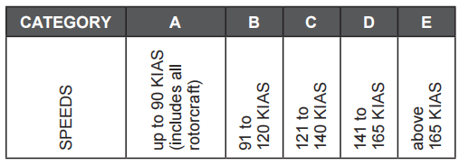
Aircraft approach category speeds (KIAS)

Aircraft Category SPEC VIS

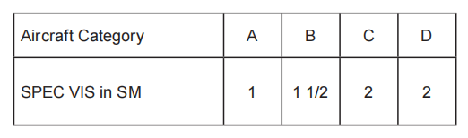
Specified visibility (SPEC VIS) by aircraft category

Circling Approach — Speed Limits
CategoryMax Circling Speed
A90 kt
B120 kt
C140 kt
D165 kt
ENo limit published
Exceeding the category speed during a circling approach may take the aircraft outside the protected area.
IFR Cruising Altitudes CAR 602.34
Below 18 000 ft ASL (Low-Level)
Magnetic track 000° – 179° (Eastbound)Odd thousands
Example eastbound3 000 / 5 000 / 7 000 ft
Magnetic track 180° – 359° (Westbound)Even thousands
Example westbound4 000 / 6 000 / 8 000 ft
On LO charts: travelling in the direction of the arrow = even altitudes.
Against the arrow = odd altitudes.
At and Above 18 000 ft ASL
FormatFlight Levels (FL)
Eastbound (000° – 179°)FL 180, FL 200, FL 220...
Westbound (180° – 359°)FL 190, FL 210, FL 230...
Altimeter setting above 18 000 ft29.92 in Hg (STD)
Transition to Flight Levels at 18 000 ft ASL in Canada. Set altimeter to 29.92 in Hg when climbing through transition altitude.
Quick Reference Numbers
VOR Checks
VOT± 4°
Ground± 4°
Airborne± 6°
Visual± 6°
Dual VOR± 4°
Published accuracy± 3°
GPS Satellites
3D fix4
RAIM5
FDE6
En route CDI± 5 NM
Terminal CDI± 1 NM
Approach CDI± 0.3 NM
Inspections
Altimeter tol.± 50 ft
Pitot-static24 mo
Compass12 mo
Transponder24 mo
GNSS DB28/56 days
IFR currency6 mo / 6 apch
Key Distances
1 NM6 076 ft
LOC coverage (±10°)18 NM
LOC coverage (±35°)10 NM
MSA radius25 NM
TAF coverage5 NM
RMKS section10 NM
NDB Checks
Approach accuracy± 5°
En route accuracy± 10°
Freq range190–515 kHz
Coastal refraction< 30° to shore
Fuel Reserves
Piston + alternate45 min
Piston, no alt.45 min
Jet + alternate30 min
Jet, no alt.30 min
Clearances / Timing
Earliest clearance before start5 min
Close FP (no SAR time)1 hr after ETA
Close itinerary24 hr after ETA
TAS change notify ATC≥ 5%
Mach change notify ATC≥ 0.01
DME / Control Zones
DME tolerance± 0.5 NM or 3%
CTZ civil (with TCA)7 NM radius
CTZ civil (no TCA)5 NM radius
CTZ ceiling3 000 ft AAE
Military CTZ10 NM / 6 000 AAE